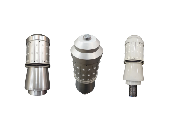
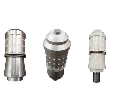
Wingoil Fully Dissolvable & Disintegrating Frac Plug
Product series: Wingoil Frac Series
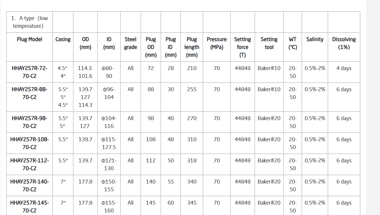
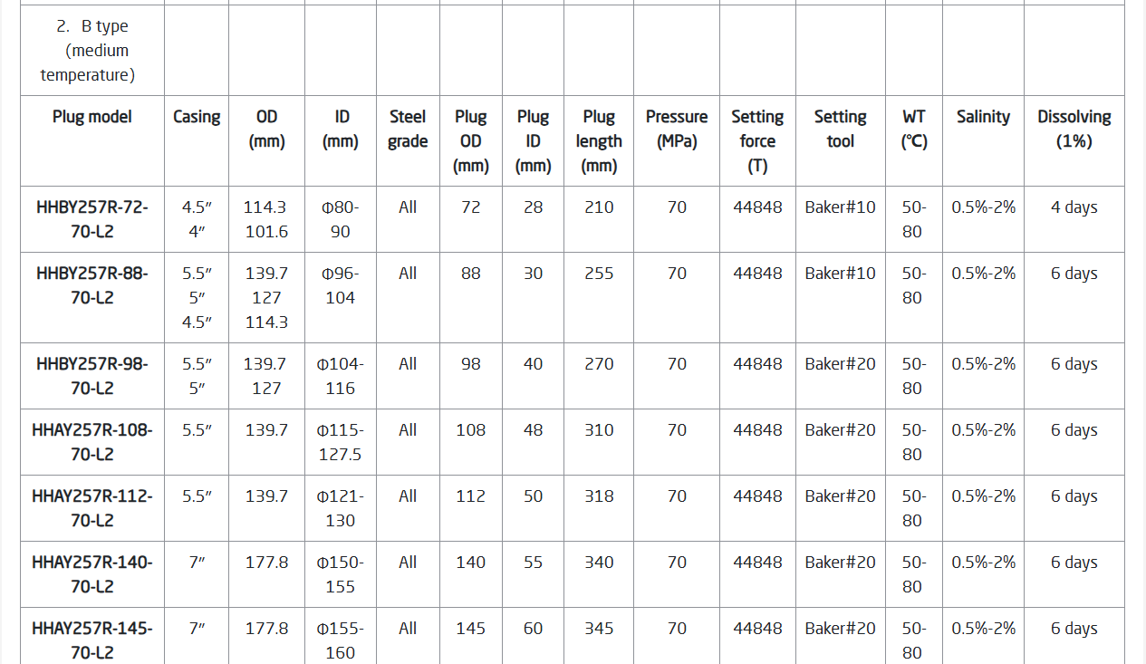
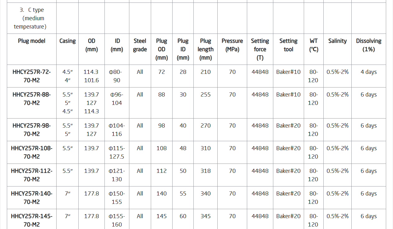
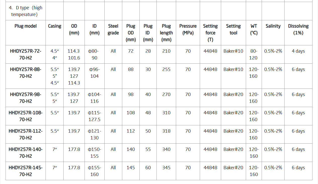
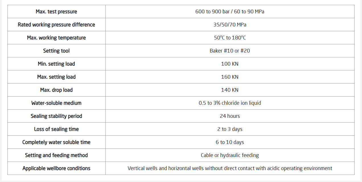
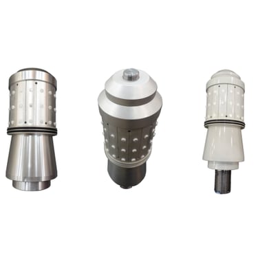
The Wingoil fully dissolvable frac plugs are made of high-strength dissolvable magnesium alloy, with a max. test pressure of 60 to 90 MPa and an operating temperature range of 50°C to 180°C.
Description
Other temporary plugging operations.
Completion casing open hole layered sectioned fracturing construction.
Mainly used in vertical or horizontal well casings for layered section fracturing.
Applications
Features
The structure is simple and user-friendly, offering various specifications—Φ72, Φ85, Φ88, Φ98, Φ102, and Φ108—to accommodate staged fracturing requirements for different well diameters.
High Compressive Strength: Designed to withstand operations in medium and deep wells, with all components, including sealing parts, made from degradable materials that leave no residue after dissolution.
Specialized Fracturing Bridge Plug: Equipped with a central production channel, allowing direct production after fracturing. The plug fully dissolves in wellbore fluid, eliminating the need for drilling.
Compact Design: Features a short body length and minimal seat-seal displacement.
Enhanced Performance: Compared to rubber-tube-sealed soluble bridge plugs, it offers better temperature adaptability—performing well in both lower and higher temperature ranges—and ensures thorough dissolution post-construction.
Drillability: In special cases where removal is required, the plug can be efficiently drilled out using standard high-performance milling tools.
Adaptability in Non-Water Environments: For non-water operation wells, the plug can be used alongside acidic rapid-degradation fluids.
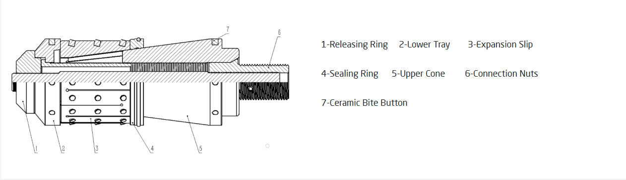
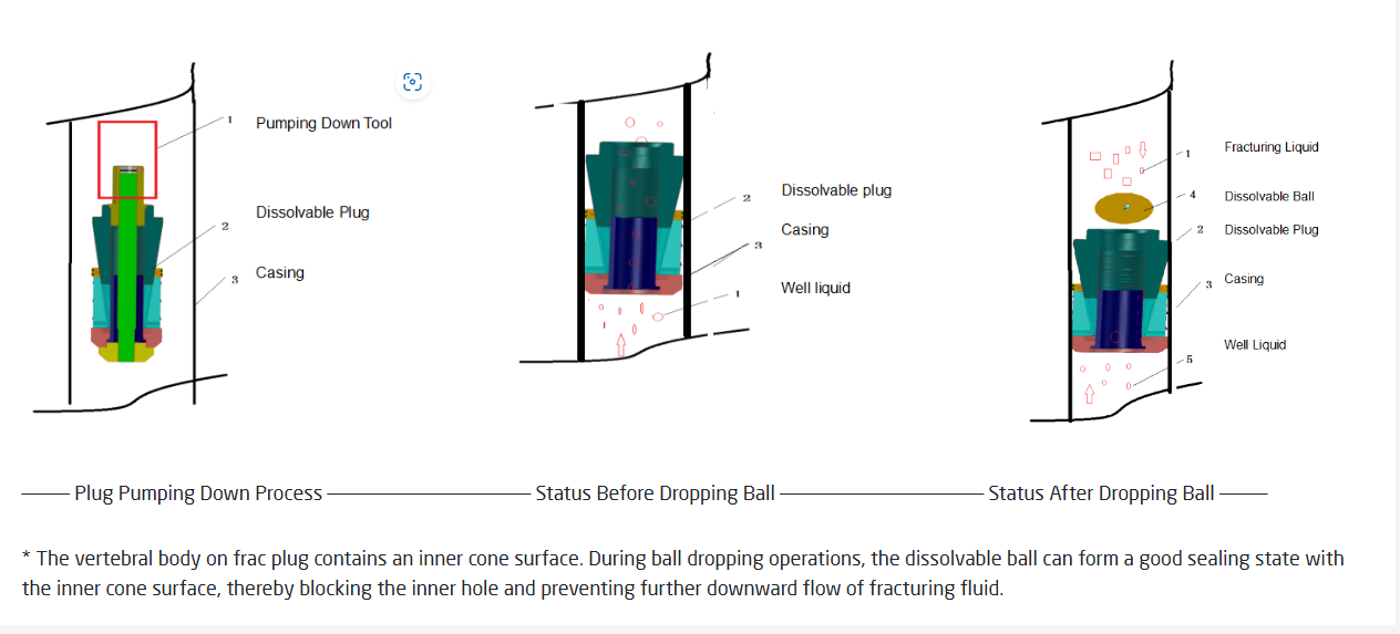
Working Principle
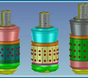
The Wingoil all-metal dissolvable frac bridge plug is a temporary isolation frac plug designed and manufactured using water-soluble materials. It consists of components such as a throwaway screw, top wire, ceramic column, O-ring, sealing ring, lower support, slips, and take-off ring.
1. Installation:
The plug is attached to the adapter of the plug-feeding tool using the throwaway screw. It is then delivered to the designated setting position via cable or coiled tubing.
2. Positioning and Activation:
Once positioned using CCL calibration, the plug is activated either by igniting the plug-feeding tool or by pumping liquid from the surface. The generated gas pressure from a gunpowder column or hydraulic pressure from the pumped liquid pushes the vertebral body. The take-off ring restricts the movement of the mandrel, allowing relative displacement between the mandrel and vertebral body.
The vertebral body moves downward, pushing the sealing ring and slip cone.
The sealing ring deforms under thrust, expanding to seal the sleeve’s inner cavity while the inclined surface of the slips extends outward.
The slips bite into the casing’s inner wall to ensure anchoring.
3. Setting and Disconnection:
When the applied thrust reaches 120-130 KN or higher, the plug is fully set and anchored. The mandrel of the plug-feeding tool is then disengaged by disconnecting the hand-off screw, allowing the plug-feeding tool to be retrieved.
4. Fracturing Operation:
After setting, the inner cavity of the plug is sealed by an inserted sphere, creating a one-way flow channel. Fluid can only flow upward from the bottom, while the upper fluid is blocked, ensuring the bridge plug remains sealed during fracturing.
5. Post-fracturing:
Once fracturing is completed, fluid from the lower interval flows through the one-way channel for normal blasting or production. During this process, the Wingoil all-metal dissolvable bridge plug degrades and dissolves in the wellbore fluid, leaving no residue.
Operation Manual
Before deploying the bridge plug for plugging operations, ensure the wellbore is thoroughly cleaned, scraped, and cleaned to guarantee unobstructed flow.
Inspect the assembly of the plug-feeding tool carefully prior to lowering it into the well. All connections must be secure, and the outer cylinder of the tool should fully abut the mandrel shoulder.
When lowering the tool using a pipe string or cable, maintain a controlled speed not exceeding 30 m/min. Sudden lifting, abrupt release, or strong impacts are strictly prohibited. If pumping is used, the recommended displacement is 1.8–2 m³/min.
For staged fracturing wells, accurately measure the displacement to ensure the complete removal of sand from the casing in the plugging section.
During hydraulic plug-feeding operations, increase the pump injection pressure incrementally in 5 MPa steps, pausing for one minute at each step to achieve stable setting.
Operation Precautions
Store the tool in a cool, dry environment.
During transportation, ensure it is securely placed in a protective box, avoiding any strong collisions.
Do not use the tool if there is any local deformation or abnormality on its outer surface.
The bridge plug must not be deployed until the wellbore sand has been thoroughly cleaned following fracturing sand plugging.
In the event of abnormal conditions during horizontal well pumping, analyze the cause. If early setting is ruled out, adjust the displacement as needed to continue pumping.